One of my cars did not have a hydraulic filter when I purchased the car. During the preparation of the car to make it roadworthy I had problems with the LHS high-pressure circuit. It did not produce enough power to lift the car. For this reason I disassembled the high-pressure circuit and thoroughly cleaned the hydraulic pipes and replaced the rubber hoses. This left me with a pump, I did not trust, and a high-pressure regulator with a green sphere (on a red LHS system). I decided to overhaul the pump myself as I estimated this could be done (after being encouraged by a friend).
In the past Citroen sold a tool for removing the pump housing (2282T) which I do not have. Therefor I started with making a tool to remove the pump housing. The problem was that in the pump body screws were used with a diameter of 8mm but a thread pitch of 1mm in stead of the common 1.25mm for Metric M8 screws. For this reason I used the lathe to produce three screws, diameter 8mm, total length 8cm with on one side a thread with a pitch of 1mm and the other side with a pitch of 1.25mm. Furthermore I did bent a strip of 3cm wide and 4mm thick to fit around the pump body. Additionally a piece of scrap plywood (11x10cm 18mm thick) served as the top.
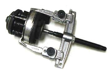
Remove the nut from the pulley and remove the pulley, dust cover (carefully) and the steel plate as well as some screws and the small triangular mounting plate. With the three homemade screws fitted and the strip put in place, the plywood was brought in position as shown on the photo. Then gradually the screws were tightened, one by one, pressing the housing off the pump body.
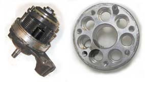
After removing the pump housing it was obvious that the pump was not in a good condition. It was extremely dirty. Furthermore two mechanical problems showed (see photo). One cylinder was stuck in the low position, not delivering any pressure. More seriously however was a crack between two cylinders in the aluminum pump body. This is a common problem with these pumps. Always check this first before putting effort into the rest of the disassembly. For me it was clear that I had to use another pump for the overhaul.
I started over again with a different pump. This pump had always run on LHM and was in a very good condition. The wear of the pump parts was not excessive and the aluminum pump body was in a very good condition.
I used a pulley extractor to remove the spindle from the pump. Be careful not to lift the pistons out off the cylinders in this stage as the pistons and cylinders are couples and should be kept together. I also kept the pushrods with the cylinder in order not to end up with the tedious process to determine the accurate length of the rods as described in the repair manual. All other parts can be mixed.
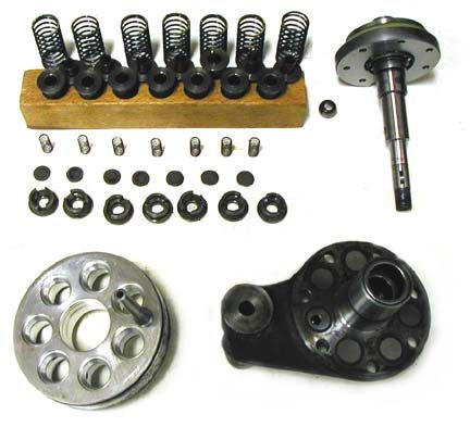
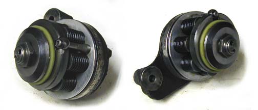
After removing the pistons and pushrods with their springs, the cylinders can be removed from the aluminum pump body using a wooden hammer. Also the endplate can be removed by using this wooden hammer. On the photo the complete disassembled pump is visible. as can be seen the pushrods, pistons and cylinders are kept together in a wooden block. All parts were cleaned thouroughly.
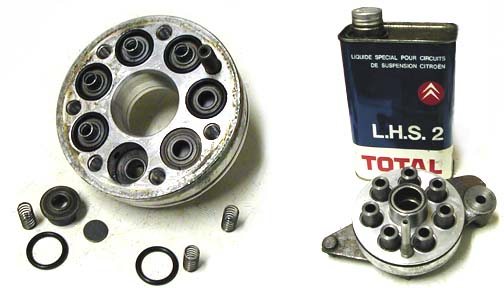
After the cleaning new seal rings were inserted in the aluminum block and the cylinders were put in place at their original positions after using some LHS (or LHM if the pump should be operated with LHM) to make it easier to insert them. After that the valves, valve guides, springs and seal rings were put in place again. On the endplate the seal ring was also replaced. The endplate was put onto of the pump body and screws were tightened with 3.5 mkg (34.335 N.m = 25.32 ft.lbF = 303.8 in.lbF).
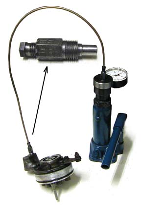
After the assembly of the pump body this assembly can be tested for leaks. I connected the pump using a small adapter I made (as can be seen in the photo) so that I could use a standard hydraulic pipe (4.5mm). The pressure was produced using the sphere tester in combination with an adapter to be able to connect a hydraulic pipe. During the testing some LHS fluid leaked out off some cylinders due to valves not closing perfectly. Personally I think this is not dramatically. I carefully checked the seals between the pump body and endplate. These should not leak any fluid as this will cause problems when the pump is mounted.
After testing the pistons, springs and pushrods are remounted in the right order (piston 1 in cylinder 1 ect...). Citroen did sell special clamps to hold the piston in the cylinder. I did this without the clamps. With a little bit of care this is possible by gently pressing the axle (with a replaced seal-ring) down while ajusting the position of the pushrods.
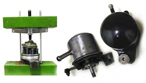
The next stage is to press the axle in place. I did not have a proper press for this so I produced a temporary press using some scrap iron (see photo) in combination with parts of the pulley extractor. This worked fine for pushing the axle in place. I used the same press and a wooden cup to press the pump housing in place. Take care that the fluid inlet is positioned correctly as shown on the photo.
After repainting the pump with 2-pack black paint the pump was ready to be mounted.
![]()